


For a little fun, we decided to tinker with cardiac monitoring and simple prototyping of wave morphology via common components. After we finishing, we wanted to post our little project to share with the world… so if you’ve got a chipKIT lying around and some free time, see if you can build your own pulse meter!
In order to build this project, you’ll need following things.
- 1 Easy Pulse sensor
- 1 chipKIT Uno32 board
- 1 chipKIT Basic I/O Shield
- 3 male/female jumper wires (20 cm long)
- Power supply source (9V DC wall adapter or battery with a clip)
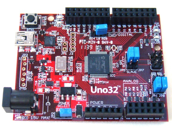
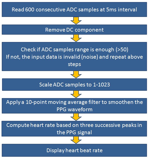
The OLED display on the Basic I/O Shield is driven through SPI interface. This requires the JP4 jumper on chipKIT Uno32 board be placed on the RG9 position so that the SPI SS function is available on Pin 10. Read our tutorial Exploring the chipKIT Uno32 for more details on jumper functions and settings on the Uno32 board. The following picture shows the required jumper settings on Uno32 board for this project. The firmware of this project is based on the same algorithm as used in our previous project PC-based heart rate monitor. The algorithm used by the PC application before is now implemented in the firmware of Uno32. The following flowchart shows the algorithm used to compute the pulse rate. Now plugin the Basic I/O shield on top of the Uno32 board and connect the Easy Pulse sensor power supply and the analog PPG output pins to the I/O shield as shown in the following figure.
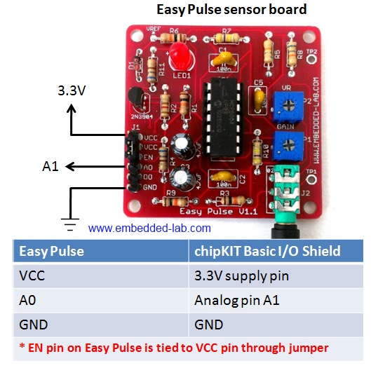
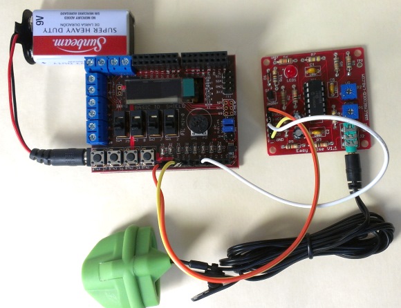
The Easy Pulse board is powered with 3.3V power supply from the I/O board header pins. The analog pulse output from Easy Pulse is connected to analog pin A1 of Uno32 through headers available on the I/O shield. The analog pin A0 of Uno32 may not be used for feeding Easy Pulse output because it is already hard-wired to the potentiometer output on the I/O shield. The following picture shows the complete setup of this project.
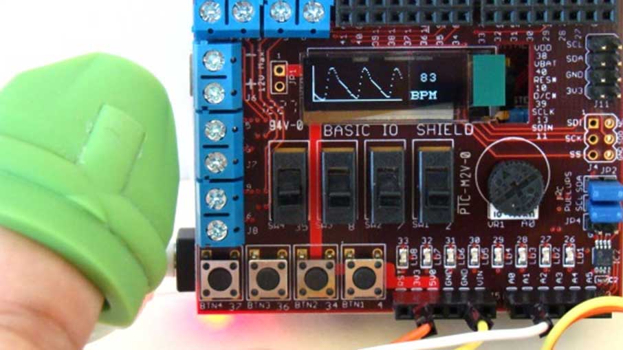
The PPG waveform and the pulse rate (in beats per minute, BPM) are both displayed on the OLED screen of the I/O shield. The Uno32 sketch uses the chipKIT I/O Shield library to display data on the OLED. Unzip the downloaded sketch folder and upload the sketch named P3_Uno32_PulseMeter.pde to the Uno32 board.
After the sketch is uploaded, power the Uno32 board through a DC wall adapter or any other external power supply that could be used to power the Uno32 board. Using USB power source is not recommended as some USB ports do not supply enough current for Easy Pulse sensor, in which case the performance of the sensor would be poor. When the sensor is unplugged, the range of ADC would not exceed 50 counts (described in the algorithm) and the pulse meter displays “No Pulse Signal” message on the OLED screen as shown below.
Now wear the Easy Pulse sensor on a finger tip and adjust the P1 potentiometer on the Easy Pulse to 1/4th position from left. The PPG waveform and the pulse rate should now display on the screen. The screen is refreshed in every 3 seconds. If the PPG signal appears clipped at the peak values, consider decreasing the gain of the filter circuit on the Easy Pulse board. This can be done by rotating the P1 potentiometer counterclockwise. Similarly, if you see the “No Pulse Signal” message even after wearing the sensor, you should consider increasing the gain by slightly turning the potentiometer clockwise. Read the Easy Pulse document for more details on the function of P1 and P2 potentiometers of Easy Pulse.